Scanning
Laser scanning uses a beam of light to trace the contour of an object. The beam then moves on a fraction of a millimeter and records another contour. If the original sculpture was not cut into sections then the probe and the laser would not be able to scan around the legs. The areas where other bits of sculpture are in the way are termed "under-cuts".
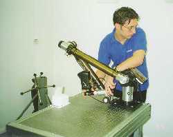
The rear leg was laser scanned by 3d Scanners
Here Nic Alimaras is using the laser scanner to scan the leg.
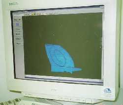
Surfacing
Above is also a rendered image of the data collected for the leg.
Manufacture
The leg was being made byThe Innovative Manufacturing Centreand UMAK Limited. The scanned data of the head was being turned into .stl (stereo-lithography) files and was be made by rapid prototyping.
The files are made of tiny triangles that cover the scanned area. The smaller the triangles then the more data captured. Some of the scanning cannot capture every single point on the object but if there is the tiniest gap in the computer scan then the manufacturing process will not work. This means gaps have to be filled manually. If your object is very detailed then this can take some time.
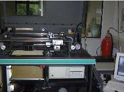
The process used is a form of RP (Rapid Prototyping) called LOM -Laminated Object Manufacture.
The computer model is sliced in 0.1mm layers. A laser cuts the contour of an object on a 0.1mm layer of paper then another layer is laid and the next contour is cut.
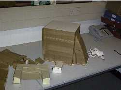
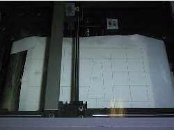
If the machine was starting from the base a standing figure then it would begin by cutting the soles of the feet
, then the ankles, the knees etc. Each layer is only a tenth of a millimeter thick so it would
take 500 layers to make a foot! Squares are also cut around the object so that the area not part
of the sculpture is supported and can be broken away. For example, if your arms were outstretched
then it would support the contours cut for these.
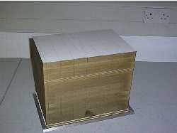
Finished Part

The final section is about 100 x 40 x 50 centimetres. 5 LOM parts have been glued together and steel rods inserted down the leg to ensure that the parts do not separate. The parts were treated so that they are stable in a range of temperatures and humidities. This is so that the layers do not delaminate (come apart).
Steve Upcraft (IMC), Simon Graham (Umak) and Paul Webber (IMC) can be seen here.